Aem Gauge Wiring Diagram

Detroit Ddec 4 Ecm Wiring Diagram, How to start a Series 60 Detroit Swap Mawk wiring 12.7 14L DDEC IV, 3.78 MB, 02:45, 32,122, Bob Brenner, 2019-03-14T23:37:55.000000Z, 19, Ddec Iv Ecm Wiring Diagram, schematron.org, 5100 x 3300, png, ddec ecm schematic diesel lt9500 freightliner schematics cableado injector justanswer celect amp3 6v92 fuse floraoflangkawi, 20, detroit-ddec-4-ecm-wiring-diagram, Anime Arts
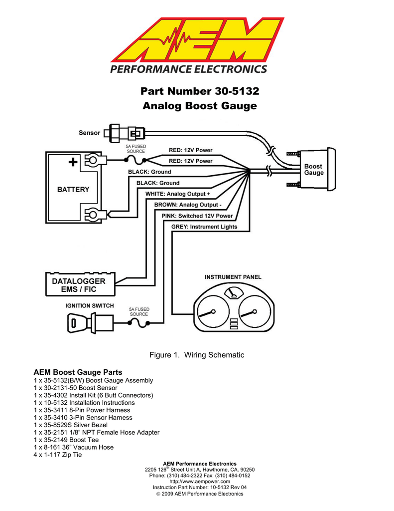
The aem gauge is ideal for all vehicles including carbureted applications and engine dynamometers. The locating tabs on the side of the connector should be nearest the center of the gauge. Mount the sensor as shown in figure 2. Aem offers a variety of aftermarket wiring harnesses from plug and play applications to programmable options.
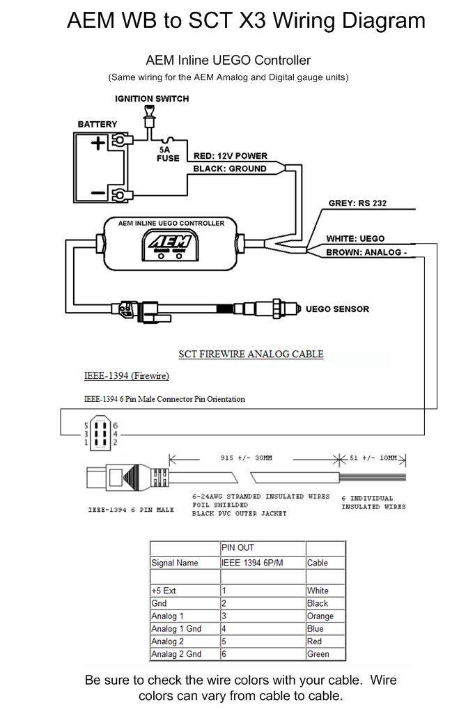
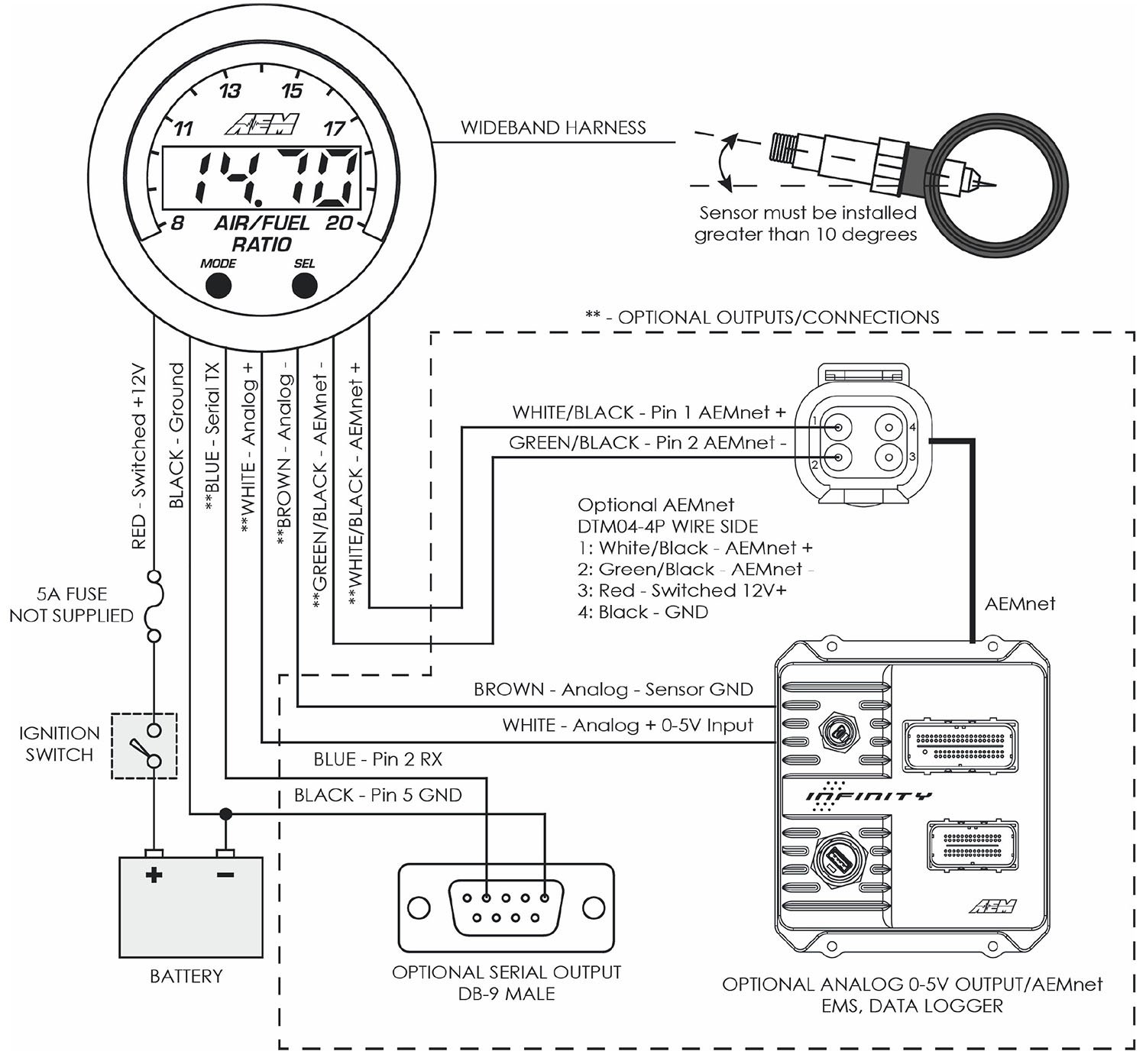
The aem gauge is ideal for all vehicles including carbureted applications and engine dynamometers. Wiring installation diagram to populate optional extras, use jst p/n: To properly read a cabling diagram, one offers to find out how the particular components inside the system operate. For instance , if a module is powered up also it sends out a signal of fifty percent the voltage in addition to the technician will not know this, he would think he provides an issue, as this individual would expect a 12v signal. Aem. to wire an oil pressure gauge, make sure to get a copy of the wiring diagram for the specific brand and model of the device. Aem air fuel gauge wiring diagram. Configure the gauge as desired by changing the gauge face and or bezel. The blue wire from the aem uego gauge shall be connected to pin #2 (rx) on the serial port for receiving data. Because the aem gauge utilizes the internal aem uego controller and bosch uego sensor, it is accurate and repeatable to 0. 1 of.
Aem Digital Oil Pressure Gauge Wiring Diagram

Aem Uego Wiring Diagram

Aem Fic Wiring Diagram - 2

Aem Digital Oil Pressure Gauge Wiring Diagram

Aem Air Fuel Gauge Wiring Diagram

Aem Digital Oil Pressure Gauge Wiring Diagram

How to wiring AEM A/F gauge on 2017 Fxsvho
Aem X Series Wideband Wiring Diagram - pinoyfaves

Aem Air Fuel Gauge Wiring Diagram

Aem Air Fuel Ratio Gauge Wiring Diagram

